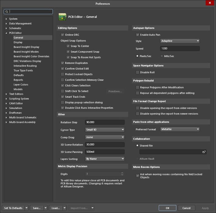
Altium Designer 25.6.2 EDA PCB software
€0.00
Altium Designer 25.6.2 EDA PCB software crack license download Altium Designer allows you to organize an end-to-end design process, starting from entering the electrical schematic diagram and ending with the formation of files for automatic assembly of components on the board.
Altium Designer 25.6.2.33 x64 full crack license working tested download Altium Designer 25.6.2 EDA PCB software
Program Altium Designer is a software package electronic design ECAD or EDA (an acronym for Electronic Design Automation and able automation electronic design) is for printed circuit board (Printed Circuit Board or the abbreviation PCB), and also integrated circuits, digital, programmable (FPGA stands for Field-Programmable Gate Array) is used. This software in the year 1985 with the name of the Protel Designer, and for a retro DOS was presented and two years later, software, Protel Schematic, as the design section and edit the schematic was published after the presentation of the version of Protel DXP, name this collection is nurtured, the current was changed.
Facilities and features of the software Altium Designer :
– PCB design with parts support for Embedded and embedded and … management, advanced layers, etc., trace route, auto and…
– Analyze analog circuits using Spice
– The possibility, design, and implementation schematic
– Has a library, a very complete parts with different classification suitable
– Having the tools to complete the coding and the design of the FPGA with the ability to simulate and debug VHDL (a language describing hardware) and…
– Ability to output as a three-dimensional circuit
– There are plug-ins, multiple direction, then, dye removal efficiency new features to the software
– Support for all companies, a manufacturer of printed circuit
Altium Designer allows you to organize an end-to-end design process, starting from entering the electrical schematic diagram and ending with the formation of files for automatic assembly of components on the board. All documents related to the development of one product are combined into a common project, which allows you to manage complex developments as simply as possible.
The most simplified implementation of creating hierarchical and multi-channel structures allows you to transform huge and complex circuits into a set of the simplest subcircuits.
Navigation tools allow you to track multi-pin connections between sheets of a multi-sheet project. All subcircuits of the hierarchical structure belong to a certain area on the board (Room) and combine the components of the circuit into clusters of components on the board, and all buses on the circuit will be combined on the board into a class of circuits, which significantly simplifies the designer’s work. Working with a large set of project documents is simplified by the presence of a miniature viewing window that appears when you hover the cursor over the document name in the project structure.
Similarly, when selecting a port on a multi-sheet diagram, miniature images of sheets containing the mating parts of the selected port appear on the screen.
When developing electrical schematic diagrams, it is possible to set the design parameters of the future board, for example, to form classes of circuits and groups of components, and to describe differential pairs. Restrictive rules can be set directly in the diagram for the created classes of circuits and differential pairs, such as the length and width of the conductor, as well as the impedance value.
All objects of the diagram editor have user settings, which allows them to be adapted to the requirements of any national standard, including GOST RF. Flexible settings and creation of user settings allows documentation to be prepared in strict accordance with GOST requirements.

The program libraries contain more than 80,000 components and are constantly updated, and it is possible to import ready-made libraries from PCAD 2000-2006.
In addition, it is possible to create your own libraries of symbols, footprints, 3D models and text SPICE models for modeling. A component stored in the Altium Designer library has all the information necessary to solve design problems at all stages of design.
A component library is needed, and after the activation of Altium Designer key file is completed, you can store it as a database. In this case, the description of components is performed in the DBMS (all modern systems are supported, MS SQL Server, Oracle, etc.), and the components referenced by the database are stored in separate libraries in a format suitable for the program.
This approach provides the most complete control over the library and allows you to establish a relationship with other enterprise databases (warehouse, purchases).
Library elements can be developed in the wizard mode, which allows you to obtain a ready model with minimal time expenditures by sequentially entering information about the component. The footprint editor has an IPC Footprint Wizard for creating footprints in accordance with the IPC-7351 standard. The symbol editor has an XSpice Model Wizard for creating Spice models.
The printed circuit board editor allows you to work both in the classic form, with layer-by-layer display of objects on the board, and in the three-dimensional display mode. This feature is fundamentally new for programs of this class and purpose. In Altium Designer, you can open a ready-made REM unit with one or more boards installed in it for free and then develop the board taking into account its interface with mechanical parts and other boards.
Changes made to one of the board cells or mechanical parts can be instantly transferred back to MCAD. Similarly, by correcting a case part or board in MCAD, by updating the models in the program, all changes are entered into the board editor. In the board editor, you can constantly switch between 2D and 3D mode, taking into account the conjugacy of parts in the assembly and making changes on the board plane.
Related products
Geology
Mathematical
Uncategorized
Uncategorized
Uncategorized
Uncategorized
Mining Industry
Uncategorized
Uncategorized
Science Research
Uncategorized
Uncategorized
Uncategorized
unlimited find
Science Research
unlimited find
Geology
Geology
Uncategorized
engineering softwares
Cad/Cam
chemistry software
Uncategorized
Uncategorized
Uncategorized
Simulation
Uncategorized
Uncategorized
Biomedical
Oil and Gas
Uncategorized
Uncategorized
Uncategorized
unlimited find
engineering softwares
Uncategorized
Science Research
Mathematical
Uncategorized
Cad/Cam
Uncategorized
Uncategorized
Uncategorized


