Altium Designer 24
€1.00
Altium Designer 24,Altium Designer 2024 is a comprehensive system for the automated design of electronic modules based on printed circuit boards, which allows you to perform a full range of design tasks
Download Altium Designer 24.0.1 Build 36 PCB Design Software
Download Altium Designer 24
Altium Designer is a comprehensive system for the automated design of electronic modules based on printed circuit boards, which allows you to perform a full range of design tasks: from creating a functioning concept to releasing a complete set of design and production data.
Altium Designer is the most common PCB design system among electronics engineers and designers. Altium Designer is an affordable, efficient and modern software with a single user interface, with the management of a simple and clear licensing system. A single Altium Designer data model allows you to quickly and efficiently design new electronic products. The optimized unified user interface of all editors (UGO, footprint, circuit, board, design documentation, etc.) increases the productivity of the design process and eliminates the typical difficulties and errors caused by manual data transfer between editors.
Key features of Altium Designer:
-A unified platform where all stages of the design of an electronic device are carried out.
-Creating electrical circuits. Altium Designer supports bidirectional communication between the circuit and the board, which ensures the unity of the user interface and data model for the entire design process and increases its efficiency.
-Component management. A single model of each component, in which there are all the necessary components: UGO, seats, 3D-model and behavioral models for the analysis of functioning.
-Verification of the project. The built-in XSPICE mixed analog and digital analysis editor and signal editor allow for AC analysis, transient analysis, calculation of the operating point, sensitivity analysis to parameter changes, Monte Carlo analysis and other types of analysis.
-Designing a topology where tools have a logical structure and allow you to place and move objects in various modes.
-Supports flex-rigid boards. Altium Designer simplifies the definition and editing of areas with a flexible-rigid stack of layers consisting of different materials and having different thicknesses, which allows you to create flexible-rigid structures on one board.
-Designing devices from several electronic modules. Altium Designer allows you to design an assembly consisting of many connected boards, supports device designs from several electronic modules.
-Interactive tracing. The modern capabilities of the board editor allow tracing of single conductors and differential pairs in various placement modes and adjust the length of the conductors.
-Interaction with mechanical CAD systems. The NATIVE 3D ™ graphics engine allows seamless interaction between the design of the electronic and mechanical parts of the product.
-Data management includes the functions of blocking, visual comparison of document changes and revisions.
-Formation of design and production documentation for ESKD. Data for production and assembly are generated in batches using Output Job files. Draftsman tools allow you to quickly get a set of documentation for production and assembly.
Overview of Altium Designer Features
Change thermal connection styles for pads and vias on the fly.
Discover to how easily route both rigid and flex designs by following the countors of your board.
Improved features in Draftsman make it even easier to create your PCB fabrication and assembly drawings.
Move components on your board without having to reroute them.
Organize your design exactly as you want with no layer restrictions.
Explore how Altium Designer makes it easy to define the materials in your layer stack.
Manage multiple impedance profiles for stripline, microstrip, single or differential pairs.
System Requirements:
Minimum System Requirements
Windows 11, 10 (64-bit only), or Windows 8.1 (64-bit only)
Windows 7 SP1 (64-bit only) is still supported, although not recommended.
Intel® Core™ i5 processor or equivalent
4GB RAM
10GB hard disk space (Install + User Files)
Graphics card (supporting DirectX 10 or better), such as GeForce 200 series/Radeon HD 5000 series/Intel HD 4600
Monitor with at least 1680×1050 (widescreen) or 1600×1200 (4:3) screen resolution
Adobe® Reader® (version XI or later for 3D PDF viewing)
Up to date Web browser
Microsoft Office 32-bit or 64-bit
Altium Designer 24
Altium Designer 24 is poised to elevate electronics design to unprecedented levels with significant emphasis on enhancing efficiency, fostering collaboration, and overcoming the ever-growing challenges of complex product designs.
PCB CoDesign
Dramatically compress design cycles and accelerate the overall design process, which is required to help meet scheduling milestones, significantly reduce layout time, and achieve faster time to market. Real-time notifications and comparison tools ensure quick conflict resolution.
Ansys CoDesign
Streamline design changes between layout and simulation with the ability to seamlessly exchange data with Ansys, communicate and implement design changes based on simulation results, and access simulation reports without having to leave Altium Designer.
New Constraint Manager
Ensure adherence to design rules and constraints, reducing costly errors and revisions. Constraint manager optimizes workflows, minimizes risks, and lowers production costs in the fast-paced electronic design landscape.
Harness MCAD CoDesign
Optimize harness implementation and detect potential problems for wiring in electronic enclosures by keeping harness designs synchronized between Altium Designer and PTC Creo® and Dassault Systemes SOLIDWORKS®. Easily import 3D wire harness models into multi-board assemblies
Harness & Multi-Board System Design
Prevent costly manufacturing errors with automated design checks when working on complex harnesses. Design multiple PCBs and harnesses in a single environment, facilitating accurate system design communication to manufacturing. Automatically generate documentation and bill of materials for harness components.
Download Altium Designer 24
PCB CoDesign Improvements
Altium Designer 24
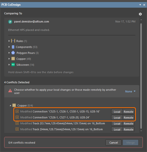
Enhanced Copper Conflict Display and Resolution
Conflicts of copper objects are now grouped in pin-to-pin connection groups where applicable to ease exploring and resolving the changes.

Copper conflicts can now be resolved on the pin-to-pin connection level.
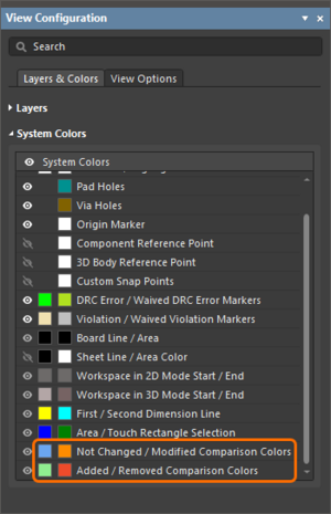
Added Ability to Configure Color Legend
In the View Configuration panel, you can now select colors for objects that have been added, modified, removed, and not changed (unchanged objects of a pin-to-pin connection when it is selected in the PCB CoDesign panel).

Use the View Configuration panel to configure the comparison color legend.
Other PCB CoDesign UI Changes
- The pop-up that shows that the comparison is in progress now appears right after running the comparison.
- Added the ability to select and deselect entries in the change list. When an entry is selected (by clicking on it), click it again to deselect the entry and reset the object highlighting in the design space.
- The Save to Server command has been added to the menu of the Project panel’s Merged icon (
 ) shown after merging changes using the PCB CoDesign panel – show image.
 - When clicking the Save to Server button in the PCB CoDesigner panel after merging changes, only the merged PCB document is selected in the Save to Server dialog by default – show image.
- When merging the changes is run, a new pop-up showing that merging is in progress is now displayed – show image.
Related products
engineering softwares
Simulation
Simulation
Simulation
Simulation
Simulation
Mining Industry
scientific software
engineering softwares
Franc3D v7.5 simulate 3D crack growth in engineering structures
Simulation
Simulation
Simulation
Simulation
Simulation
Simulation
engineering softwares
Simulation
Simulation
Simulation
Simulation
Uncategorized
Simulation
Simulation
Simulation
Simulation
Simulation
Simulation
Simulation
Simulation
Simulation
Simulation
Simulation
Simulation
Simulation
scientific software
Simulation
Simulation
Simulation
Simulation


